
DIN 471 circlip for shafts: dimensions and groove sizes
External circlip for shafts, regular series, for shaft diameters from 3 to 100 mm. The table gives the ring and the groove it sits in; pick a size to download its CAD files.
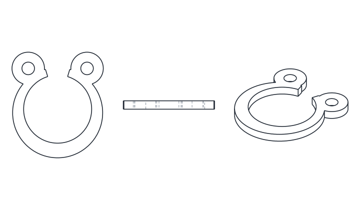
DIN 471 dimensions: external circlip size chart
| Shaft d1 | smm | d3mm | amax, mm | bapprox, mm | d5min, mm | d2groove, mm | mgroove, mm | nmin, mm |
|---|---|---|---|---|---|---|---|---|
| 3 | 0.4 | 2.7 | 1.9 | 0.8 | 1 | 2.8 | 0.5 | 0.3 |
| 4 | 0.4 | 3.7 | 2.2 | 0.9 | 1 | 3.8 | 0.5 | 0.3 |
| 5 | 0.6 | 4.7 | 2.5 | 1.1 | 1 | 4.8 | 0.7 | 0.3 |
| 6 | 0.7 | 5.6 | 2.7 | 1.3 | 1.2 | 5.7 | 0.8 | 0.5 |
| 7 | 0.8 | 6.5 | 3.1 | 1.4 | 1.2 | 6.7 | 0.9 | 0.5 |
| 8 | 0.8 | 7.4 | 3.2 | 1.5 | 1.2 | 7.6 | 0.9 | 0.6 |
| 9 | 1 | 8.4 | 3.3 | 1.7 | 1.2 | 8.6 | 1.1 | 0.6 |
| 10 | 1 | 9.3 | 3.3 | 1.8 | 1.5 | 9.6 | 1.1 | 0.6 |
| 11 | 1 | 10.2 | 3.3 | 1.8 | 1.5 | 10.5 | 1.1 | 0.8 |
| 12 | 1 | 11 | 3.3 | 1.8 | 1.7 | 11.5 | 1.1 | 0.8 |
| 13 | 1 | 11.9 | 3.4 | 2 | 1.7 | 12.4 | 1.1 | 0.9 |
| 14 | 1 | 12.9 | 3.5 | 2.1 | 1.7 | 13.4 | 1.1 | 0.9 |
| 15 | 1 | 13.8 | 3.6 | 2.2 | 1.7 | 14.3 | 1.1 | 1.1 |
| 16 | 1 | 14.7 | 3.7 | 2.2 | 1.7 | 15.2 | 1.1 | 1.2 |
| 17 | 1 | 15.7 | 3.8 | 2.3 | 1.7 | 16.2 | 1.1 | 1.2 |
| 18 | 1.2 | 16.5 | 3.9 | 2.4 | 2 | 17 | 1.3 | 1.5 |
| 19 | 1.2 | 17.5 | 3.9 | 2.5 | 2 | 18 | 1.3 | 1.5 |
| 20 | 1.2 | 18.5 | 4 | 2.6 | 2 | 19 | 1.3 | 1.5 |
| 21 | 1.2 | 19.5 | 4.1 | 2.7 | 2 | 20 | 1.3 | 1.5 |
| 22 | 1.2 | 20.5 | 4.2 | 2.8 | 2 | 21 | 1.3 | 1.5 |
| 24 | 1.2 | 22.2 | 4.4 | 3 | 2 | 22.9 | 1.3 | 1.7 |
| 25 | 1.2 | 23.2 | 4.4 | 3 | 2 | 23.9 | 1.3 | 1.7 |
| 26 | 1.2 | 24.2 | 4.5 | 3.1 | 2 | 24.9 | 1.3 | 1.7 |
| 28 | 1.5 | 25.9 | 4.7 | 3.2 | 2 | 26.6 | 1.6 | 2.1 |
| 29 | 1.5 | 26.9 | 4.8 | 3.4 | 2 | 27.6 | 1.6 | 2.1 |
| 30 | 1.5 | 27.9 | 5 | 3.5 | 2 | 28.6 | 1.6 | 2.1 |
| 32 | 1.5 | 29.6 | 5.2 | 3.6 | 2.5 | 30.3 | 1.6 | 2.6 |
| 34 | 1.5 | 31.5 | 5.4 | 3.8 | 2.5 | 32.3 | 1.6 | 2.6 |
| 35 | 1.5 | 32.2 | 5.6 | 3.9 | 2.5 | 33 | 1.6 | 3 |
| 36 | 1.75 | 33.2 | 5.6 | 4 | 2.5 | 34 | 1.85 | 3 |
| 38 | 1.75 | 35.2 | 5.8 | 4.2 | 2.5 | 36 | 1.85 | 3 |
| 40 | 1.75 | 36.5 | 6 | 4.4 | 2.5 | 37.5 | 1.85 | 3.8 |
| 42 | 1.75 | 38.5 | 6.5 | 4.5 | 2.5 | 39.5 | 1.85 | 3.8 |
| 45 | 1.75 | 41.5 | 6.7 | 4.7 | 2.5 | 42.5 | 1.85 | 3.8 |
| 48 | 1.75 | 44.5 | 6.9 | 5 | 2.5 | 45.5 | 1.85 | 3.8 |
| 50 | 2 | 45.8 | 6.9 | 5.1 | 2.5 | 47 | 2.15 | 4.5 |
| 52 | 2 | 47.8 | 7 | 5.2 | 2.5 | 49 | 2.15 | 4.5 |
| 55 | 2 | 50.8 | 7.2 | 5.4 | 2.5 | 52 | 2.15 | 4.5 |
| 56 | 2 | 51.8 | 7.3 | 5.5 | 2.5 | 53 | 2.15 | 4.5 |
| 58 | 2 | 53.8 | 7.3 | 5.6 | 2.5 | 55 | 2.15 | 4.5 |
| 60 | 2 | 55.8 | 7.4 | 5.8 | 2.5 | 57 | 2.15 | 4.5 |
| 62 | 2 | 57.8 | 7.5 | 6 | 2.5 | 59 | 2.15 | 4.5 |
| 63 | 2 | 58.8 | 7.6 | 6.2 | 2.5 | 60 | 2.15 | 4.5 |
| 65 | 2.5 | 60.8 | 7.8 | 6.3 | 3 | 62 | 2.65 | 4.5 |
| 68 | 2.5 | 63.5 | 8 | 6.5 | 3 | 65 | 2.65 | 4.5 |
| 70 | 2.5 | 65.5 | 8.1 | 6.6 | 3 | 67 | 2.65 | 4.5 |
| 72 | 2.5 | 67.5 | 8.2 | 6.8 | 3 | 69 | 2.65 | 4.5 |
| 75 | 2.5 | 70.5 | 8.4 | 7 | 3 | 72 | 2.65 | 4.5 |
| 78 | 2.5 | 73.5 | 8.6 | 7.3 | 3 | 75 | 2.65 | 4.5 |
| 80 | 2.5 | 74.5 | 8.6 | 7.4 | 3 | 76.5 | 2.65 | 5.3 |
| 82 | 2.5 | 76.5 | 8.7 | 7.6 | 3 | 78.5 | 2.65 | 5.3 |
| 85 | 3 | 79.5 | 8.7 | 7.8 | 3.5 | 81.5 | 3.15 | 5.3 |
| 88 | 3 | 82.5 | 8.8 | 8 | 3.5 | 84.5 | 3.15 | 5.3 |
| 90 | 3 | 84.5 | 8.8 | 8.2 | 3.5 | 86.5 | 3.15 | 5.3 |
| 92 | 3 | 86.5 | 9 | 8.4 | 3.5 | 88.5 | 3.15 | 5.3 |
| 95 | 3 | 89.5 | 9.4 | 8.6 | 3.5 | 91.5 | 3.15 | 5.3 |
| 100 | 3 | 94.5 | 9.6 | 9 | 3.5 | 96.5 | 3.15 | 5.3 |
Dimensions in millimetres unless stated. Select a row to load its CAD files above.
DIN 471 circlip and groove dimensions
The size is the shaft diameter d1. The ring is thinner than the groove width m, and its free inner diameter d3 is smaller than the groove diameter d2, so it grips the groove once fitted. The lugs, with their holes d5 for the pliers, point outwards. The minimum distance n from the groove to the end of the shaft is the material that has to stay behind the ring.
The CAD files show the ring in its free state. The shape of the opening and the way the ring narrows towards the lugs are drawn to look right but are not dimensioned by the standard tables, so take only the tabulated values as dimensions.
Retaining ring DIN 471 against DIN 472 and DIN 6799
DIN 471 is the ring for a shaft: it opens to go over the shaft and closes into an outer groove. For a bore, the matching ring is DIN 472, which is squeezed to go into the bore and opens into an inner groove. Where the end of the shaft cannot be reached, an E-clip to DIN 6799 pushes on from the side instead. The circlip size chart puts the shaft and bore rings side by side.
DIN 471 circlips: common questions
- What size circlip fits a 25 mm shaft?
- A DIN 471 circlip size 25. It is 1.2 mm thick, measures 23.2 mm inside before fitting and sits in a groove of 23.9 mm diameter and 1.3 mm width.
- How is a DIN 471 circlip designated?
- By the standard and the shaft diameter, followed by the ring thickness: for example DIN 471 – 25 × 1.2. Suppliers add the material and the surface finish.
- Can I take the dimensions of the groove from the CAD file?
- No. The CAD file is the ring only. Take the groove diameter d2, the width m and the edge distance n from the table and draw the groove in your part.