
Bolt CAD blocks and standard part models, with the dimension table for every size
Choose the part, the size and the length. The table gives you the dimensions, and the downloads give you the part itself: a STEP solid plus DWG and DXF views at 1:1. Everything is free and needs no account.
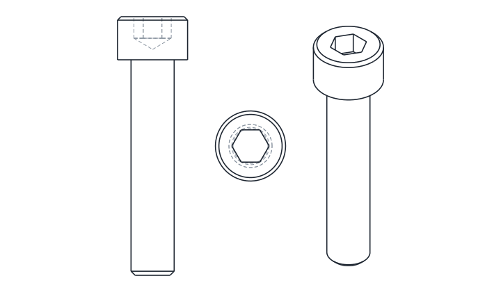
Standard part CAD models by family
- Screws 21 standards 1,724 references with CAD files
-
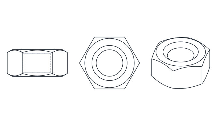 Nuts 5 standards 57 references with CAD files
-
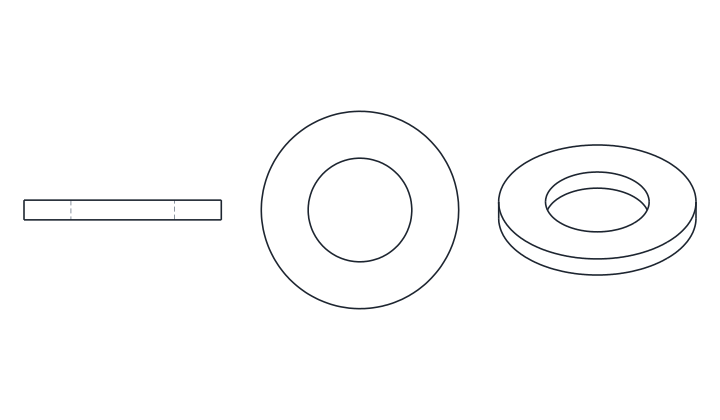 Washers 4 standards 52 references with CAD files
-
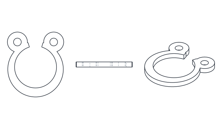 Retaining rings 3 standards 130 references with CAD files
-
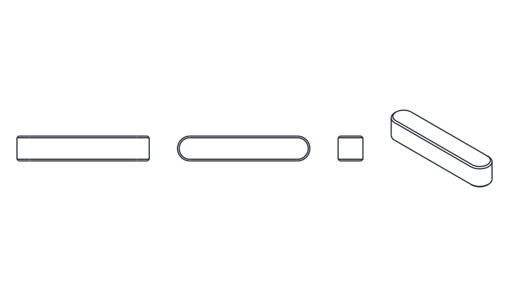 Keys and pins 5 standards 838 references with CAD files
-
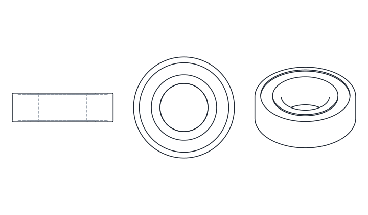 Bearings 4 standards 70 references with CAD files
-
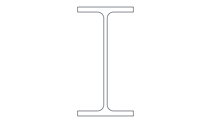 Steel sections 8 standards 367 references with CAD files
Engineering tables for threads, fits, tolerances and torque
All tools- Metric thread chart Every ISO metric thread from M1 to M64 in coarse and fine pitch, with the pitch diameter and the minor diameters of the bolt and the nut.
- Tap drill chart The drill to use before tapping each metric thread, coarse and fine, with the limits of the nut minor diameter in class 6H that the drilled hole has to respect.
- BSP thread chart Parallel British Standard Pipe threads (G) to ISO 228-1, from G 1/16 to G 4, with threads per inch, pitch and diameters in millimetres.
- UNC and UNF thread chart Unified inch threads in the coarse (UNC) and fine (UNF) series, from #0 to 1 1/2 in, with the diameters in inches and millimetres and the tap drill for each size.
- ISO 286 fits and tolerances Limits of the common ISO hole and shaft classes from 0 to 500 mm, the IT grades, and a calculator that gives the clearance or interference of a fit such as H7/g6.
- ISO 2768 general tolerances The tolerances that apply to every dimension on a drawing that has no tolerance of its own.
- Metric bolt torque chart Tightening torque and the preload it gives for hex head and socket head bolts with coarse thread, M3 to M24, calculated with the method of VDI 2230 and checked against two published tables.
- Spanner size chart Which spanner or Allen key fits a metric bolt or nut, by thread size and type of head.
Nut and bolt CAD blocks in DWG and DXF, drawn at 1:1
Every screw, nut, washer, ring, key, pin and bearing comes as a 2D file with its views drawn at full size in millimetres: a front view and a top or end view, placed in model space with no title block and no dimensions. You insert it as a block, scale 1, and it sits on the drawing at its true size.
The lines are split across four layers, so you can switch off what you do not need. CONTOUR holds the visible edges, HIDDEN the hidden edges, CENTER the axes, and THREAD the thread, drawn as thin lines at the minor diameter as on a workshop drawing. Holes and heads are true circles and arcs, not polylines, so object snaps land on centres and quadrants.
The DWG is saved as AutoCAD 2010, which current versions of AutoCAD, BricsCAD, DraftSight and most other CAD programs open without conversion. Every DWG is read back after it is written to check that nothing was lost. The DXF carries the same geometry for programs that do not read DWG.
Free STEP files of standard parts, without an account
The STEP file is a 3D solid in millimetres that opens in any 3D CAD program, such as SolidWorks, Inventor, Fusion, FreeCAD, Solid Edge or Creo. Click the file and it downloads. You do not need an account or an email address, and there is no configurator to fill in first.
Threads are cosmetic: the shank is modelled at its nominal diameter with the end chamfer, the same simplification that manufacturer CAD libraries use. A modelled helix would make each file many times heavier and slow down an assembly without telling you anything you need for the design. Steel sections come as 1,000 mm lengths that you can stretch to the length you need.
Mechanical CAD blocks you can check against the table
A CAD file is only as good as the numbers behind it, and a block drawn from an inch chart and rescaled to millimetres is still wrong. Here every dimension has to be confirmed by at least two independent published sources, such as manufacturer and distributor catalogues, before a part is generated. Where the sources disagree, the size stays out until the difference is explained. The sources for each part are listed at the bottom of its page.
The models are then built from those numbers, so the drawing and the table beside it always match. For steel sections the area, mass per metre and moments of inertia are calculated on the model itself and compared with the steel mill catalogues. A section that does not match within 1% is left out.
Where an older DIN edition gives a different dimension from the ISO standard that replaced it, such as the hexagon size of some bolts and nuts, both versions have their own files and the page shows the difference.