
DIN 6885 parallel key: dimensions and keyway size chart
Parallel key with round ends (form A), from 2 × 2 to 100 × 50 mm, with the keyway depths in the shaft and the hub. Pick the key size and the length to download its CAD files.
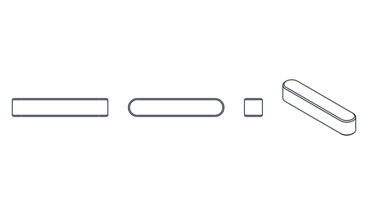
DIN 6885 keyway size chart: keys, shaft ranges and keyway depths
| b × h | hmm | dfrom, mm | dto, mm | t1shaft, mm | t2hub, mm | lfrom, mm | lto, mm |
|---|---|---|---|---|---|---|---|
| 2x2 | 2 | 6 | 8 | 1.2 | 1 | 6 | 20 |
| 3x3 | 3 | 8 | 10 | 1.8 | 1.4 | 6 | 36 |
| 4x4 | 4 | 10 | 12 | 2.5 | 1.8 | 8 | 45 |
| 5x5 | 5 | 12 | 17 | 3 | 2.3 | 10 | 56 |
| 6x6 | 6 | 17 | 22 | 3.5 | 2.8 | 14 | 70 |
| 8x7 | 7 | 22 | 30 | 4 | 3.3 | 18 | 90 |
| 10x8 | 8 | 30 | 38 | 5 | 3.3 | 22 | 110 |
| 12x8 | 8 | 38 | 44 | 5 | 3.3 | 28 | 140 |
| 14x9 | 9 | 44 | 50 | 5.5 | 3.8 | 36 | 160 |
| 16x10 | 10 | 50 | 58 | 6 | 4.3 | 45 | 180 |
| 18x11 | 11 | 58 | 65 | 7 | 4.4 | 50 | 200 |
| 20x12 | 12 | 65 | 75 | 7.5 | 4.9 | 56 | 220 |
| 22x14 | 14 | 75 | 85 | 9 | 5.4 | 63 | 250 |
| 25x14 | 14 | 85 | 95 | 9 | 5.4 | 70 | 280 |
| 28x16 | 16 | 95 | 110 | 10 | 6.4 | 80 | 280 |
| 32x18 | 18 | 110 | 130 | 11 | 7.4 | 90 | 280 |
| 36x20 | 20 | 130 | 150 | 12 | 8.4 | 100 | 400 |
| 40x22 | 22 | 150 | 170 | 13 | 9.4 | 110 | 400 |
| 45x25 | 25 | 170 | 200 | 15 | 10.4 | 125 | 400 |
| 50x28 | 28 | 200 | 230 | 17 | 11.4 | 140 | 400 |
| 56x32 | 32 | 230 | 260 | 20 | 12.4 | 160 | 400 |
| 63x32 | 32 | 260 | 290 | 20 | 12.4 | 180 | 400 |
| 70x36 | 36 | 290 | 330 | 22 | 14.4 | 200 | 400 |
| 80x40 | 40 | 330 | 380 | 25 | 15.4 | 220 | 400 |
| 90x45 | 45 | 380 | 440 | 28 | 17.4 | 250 | 400 |
| 100x50 | 50 | 440 | 500 | 31 | 19.5 | 280 | 400 |
Dimensions in millimetres unless stated. Select a row to load its CAD files above.
Choosing a DIN 6885 key by shaft diameter
The key size b × h follows from the shaft diameter: the table gives the shaft range for each size, from over the first value up to and including the second. A 30 mm shaft, for example, takes an 8 × 7 key, which covers shafts over 22 mm up to 30 mm. The keyway is cut to depth t1 in the shaft and t2 in the hub. The files come in the stock lengths of each size; for the 8 × 7 key that is 18 to 90 mm.
Shaft keyway dimensions in the drawing
The CAD files contain the key only. To draw the keyway, take the width b and the depth t1 from the table for the shaft, and b and t2 for the hub. Form A has both ends rounded with a radius of half the width, the shape left by an end mill, so the keyway in the shaft is usually milled to the same profile. The Woodruff key is the alternative for small or tapered shafts.
DIN 6885 keys: common questions
- Which key size goes on a 25 mm shaft?
- An 8 × 7 key: 8 mm wide and 7 mm high, for shafts over 22 mm up to 30 mm. The keyway is 4 mm deep in the shaft and 3.3 mm in the hub.
- What does form A mean?
- Form A is the parallel key with two round ends. Other forms of the same standard have square ends or one round and one square end; this page covers form A.